
A. Melninkaitis, D. Mikšys, M. Maciulevičius, V. Sirutkaitis
Laser Research Centre, Vilnius University, Sauletekio al. 10, LT-10222 Vilnius, Lithuania
G. Šlekys
Altechna Co. Ltd., Konstitucijos al. 23C, LT-08105, Vilnius, Lithuania
A.V. Samoylov
Institute of Semiconductor Physics, NAS of Ukraine, Prospekt Nauki 41, 03028 Kyiv-28, Ukraine

Abstract
Polymethyl methacrylate (PMMA) is a versatile polymeric material that is well suited for fabrication of many commercial optical components: lenses, fibers, windows, phase waveplates and others. Our focus is achromatic zero-order waveplates made of anisotropic PMMA which can be used to modify the state of polarization of electromagnetic radiation. Such waveplates have a broad range of application in devices where polarized laser radiation is used. For example, when tunable lasers are used or when spectropolarimetric measurements are performed, one needs an achromatic waveplate providing a specific retardation in a wide wavelength range. Herewith anisotropic properties of PMMA subjected to one-axis stretching are analyzed and the technology for manufacturing such achromatic and super- achromatic, one-axis-stretched PMMA waveplates is described. This technology excludes any mechanical processing of waveplate component surfaces. Technical characteristics of achromatic and super-achromatic waveplates manufactured of PMMA including results of laser-induced damage threshold (LIDT) measurements are discussed below.
Experimental Setup
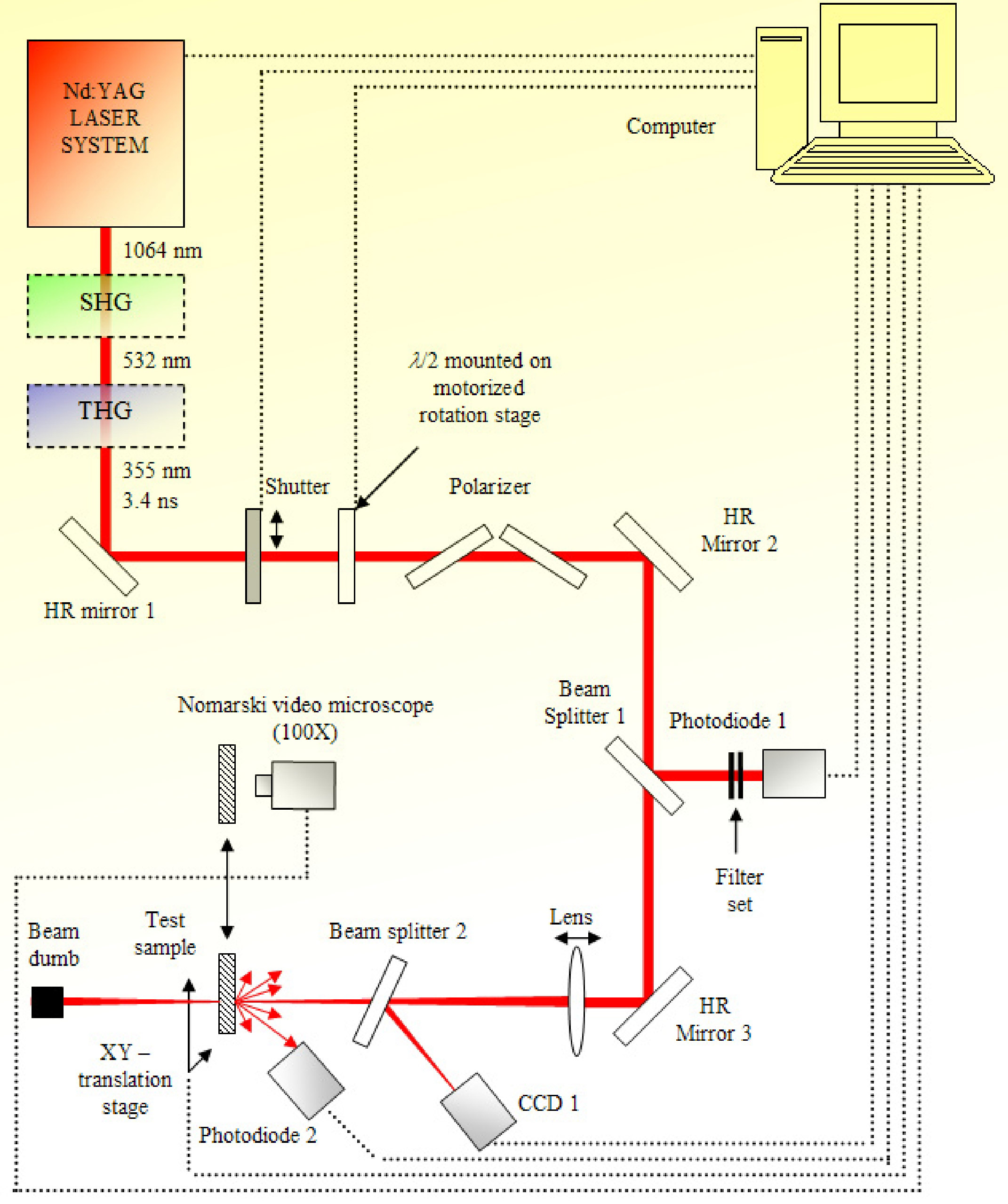
Fig. 4. Experimental Setup
Samples and Characterization
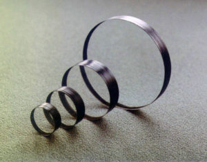
Fig.1. PMMA waveplates
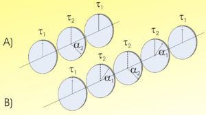
Fig.2. Design of waveplates: A) achromatic; B) super-achromatic
Waveplates (Fig. 1) are constructed using a stack of birefringent polymer plates laminated between two glass windows, each with a broadband antireflection coating.
Retardation of each polymer plate does not exceed /2 (180o) in the zero order. Optical axes of all plates are oriented relative to one another in a specific way. This construction operates with a high degree of retardation accuracy over a broad wavelength range, ensures excellent transmitted wavefront quality, while minimizing beam deviation and surface reflection losses.
The most successful combination of three plates made of the same material was proposed by Pancharatnam (Fig. 2A) [1]. The end components have coincident optical axes and equal retardation. The middle component has a retardation 2 =180o and its optical axis is rotated by an angle 2 relative to the axes of the end components. Further improvements of this design were made by Kucherov et al. for an arbitrary number of components. It was shown [2,3] that additional pairs of components (every component of a pair has a symmetrical position relative to the central one) improve considerably the waveplate characteristics. The optical axes in every additional pair of waveplates must be parallel and their retardations must be equal to 180o at the central wavelength . The five-component design is shown schematically in Fig. 2B.
The retardation of the central component is equal to 180o, and that of the end components is 180o in zero order for the central wavelength 0. The values of for 0 and the angles 1 and 2 for a specific equivalent retardation are easily calculated.
These plates are true zero-order waveplates indeed. They have better angular acceptance and less sensitivity to wavelength and temperature change than achromatic quartz-MgF2 waveplates. Optical transmittance of these achromatic waveplates is not distorted by multi-beam interference since each plate is produced of the same polymer material.
Spectral characteristics of polymeric achromatic (three components) and super-achromatic (five components) waveplates are shown in Fig. 3. For comparison, this figure also displays the characteristics of monochromatic quartz zero-order waveplates and achromatic quartz MgF2 waveplates. Here /0 is the normalized wavelength ( being the central wavelength); the retardence is measured in wavelengths. For retardation tolerance not exceeding 0.01, the range of applicability of the achromatic polymeric waveplates and the achromatic quartz MgF2 waveplates is essentially the same and is 0.850 − 1.250 . However, the shape of the spectral dependence for plates is better. The characterization of each the polymeric PMMA achromatic waveplete before laser-induced damage threshold measurements were performed using total integrated back scattering (TIS) technique and spectrophotometric transmittance measurements.
The TIS setup arranged at Vilnius University is described in [4]. As can be seen from Table 1 all the samples were with similar scattering losses and not exceeded 0.13 % (Fig. 5 A, B and C) of incident laser power at 1064 nm testing wavelengths. This is relative good value for waveplates made of five separate components. For transmittance measurements SHIMADZU (UV-3101PC) spectrophotometer was used. The transmittance properties of all samples where characterized at the same wavelengths as the LIDT tests for each waveplate. The experimental setup for laser-induced damage threshold measurements is shown in Fig. 4. The flash lamp pumped Q-switched Nd:YAG laser with wavelength doubling and tripling (=1064 nm, =532 nm and =355 nm) options was used for LIDT tests. The repetition rate of the laser was 10 Hz and pulse durations for all wavelengts were ~4.6 ns. The energy distributions and diameters for each wavelength in target plane are shown in Fig. 6. The S-on-1 [5] procedure was applied for each waveplete at given wavelength. The LIDT test results are shown in Table 1.
Results and Discussion
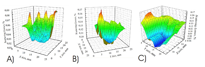
Fig. 5. Total back scattering measurements of first (A) second (B) and third (C) PMMA achromatic waveplates made of 5 components measured at 1064 nm
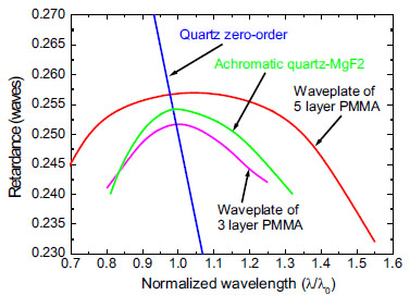
Fig. 3. Comparison of retardation behavior for quartz and PMMA /4 waveplates.
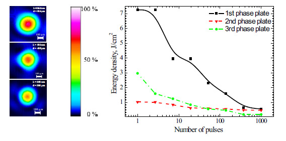
Fig.6. Testing beam diameters In target plane
Fig. 7. Characteristic damage curve
|
Nr. of Sample |
Wavelength, nm |
Transmittance, % |
Damage threshold, J/cm2 |
Scattering losses, % @1064 nm |
|---|---|---|---|---|
|
1 |
1064 |
94.7 |
0.55 |
0.04 |
|
2 |
532 |
85.4 |
0.46 |
0.13 |
|
3 |
355 |
53.1 |
0.18 |
0.11 |
References
1. Pancharatnam S. Proc Indian Acad Sci, 1995; A41:130 – 44
2. Bugaenko OI, Kucherov VA, Samoylov VS. AS 1269067. Bull. Izobreteniy 1986;41. 3.Kucherov VA. Kinematika i fizika nebesnih tel. 1986;2 (2):59.
4.O.Balachninaite et al.Absorptance and scattering losses measurements in IR range by high average power tunable radiation of optical parametric oscillator based on a periodically poled lithium niobat, Proc. SPIE Vol. 6101, 61011K, 2006
Conclusions
It is evident that S-on-1 damage threshold after 1000 laser pulses (Fig. 7.) clearly correlate with absorption/transmittance of each sample. As can be seen from Table 1 lowest damage threshold is (0.18 J/cm2) at 355 nm where absorption reaches <47%. For 1064 nm (T<5%) and 532 nm (T<14%) damage thresholds are 0.55 and J/cm2 0.46 J/cm2 respectively. This lead to assumption that damages induced in PMMA at given conditions are thermal and caused by absorption. The damage morphology study by Nomarski microscope showed that mainly all damages were damage tracks in bulk.