
Journal of Quantitative Spectroscopy & Radiative Transfer 88 (2004) 319 –325
Achromatic and super-achromatic zero-order waveplates
A.V. Samoylov a, V.S. Samoylov b, A.P. Vidmachenko c, A.V. Perekhod c
a Institute of Semiconductor Physics, NAS of Ukraine, Prospekt Nauki 41, 03028 Kyiv-28, Ukraine
b Astropribor, 31 Akad. Zabolotnoho St., 03680 Kyiv-80, Ukraine
c GAO, NAS of Ukraine, 27 Akad. Zabolotnoho St., 03680 Kyiv-80, Ukraine
Received 26 November 2003; accepted 23 December 2003

Abstract
We discuss a brief classification of waveplates including achromatic and super-achromatic ones. Anizotropic prop- erties of polymethylmethacrylat (PMMA) subjected to one-axis stretching are analyzed. The parameters controlling the value of the PMMA birefringence are identified and their typical spectral dependence is discussed. The technol- ogy for manufacturing achromatic and super-achromatic, one-axis-stretched PMMA waveplates is described, which excludes any mechanical processing of waveplate component surfaces. Technical characteristics of achromatic and super-achromatic waveplates manufactured of the same material (anisotropic PMMA) are discussed. It is shown that the use of the same material eliminates the appearance of interference ripple in transmission, which is a typical characteristic of quartz–MgF2 super-achromatic waveplates. Examples of using super-achromatic waveplates in astronomical observations are described.
© 2004 Published by Elsevier Ltd.
Keywords: Super-achromatic zero-order waveplates; Anisotropic polymethylmethacrylat; Spectral characteristics; Retardation
Introduction
Waveplates are widely used to modify the state of polarization of electromagnetic radiation. Quarter- waveplates (λ/4) transform linearly polarized light into circularly polarized light and vice versa. Half- waveplates (λ/2) rotate the polarization plane by a certain angle. Such waveplates have a broad range of application in devices where polarized laser radiation is used. When adjustable lasers are used or when spectropolarimetric measurements are performed, one needs an achromatic waveplate providing a specific retardation in a wide wavelength range.
Waveplates are manufactured both from anisotropic crystals (quartz, MgF2, etc.) and, presently, from anisotropic polymer films and sheets. Depending on the thickness of the anisotropic layer, the waveplates can be used either in zero order (retardation τ<2π) or in higher orders (τ>2π). However, it is impossible to use “multi-wave” plates in precise measurements because their optical properties are very sensitive to the wavelength, temperature, and incidence angle. The parameters of true zero-order waveplates have the weakest sensitivity to these factors, but the thickness of such waveplates for most crystals does not exceed 60 µm. For practical use, such plates are manufactured of thick pairs using the principle of “subtraction,” i.e., the orientation of the optical axes of the components differ by 90◦ and the thickness difference corresponds to the retardation needed. The plates which are made of thin anisotropic polymer films and polymer sheets and laminated between two glass windows are also waveplates of true zero order. But all these waveplates are monochromatic since their retardation is strongly spectrally dependent and has the specified value at one wavelength only.
Achromatic waveplates can be used in a considerably wider spectral range. The most widespread technique to manufacture an achromatic waveplate is based on combining two or more waveplates made of materials with different spectral dependencies of birefringence; this approach is similar to the use of two or more lens components to compensate for chromatism. A suitable pair of materials is quartz and MgF2 because of their good technological properties. Although quartz–MgF2 achromatic waveplates are widely used, their retardation remains strongly dependent on temperature and incidence angle.
Another design of achromatic waveplates consists of a combination of two or more plates made of the same material but having different orientations of their optical axes. Such waveplates have a weak retardation sensitivity to changing temperature and incidence angle as well as to external forces affecting each component equally. It was Pancharatnam [1] who proposed the most widespread and successful three-plate combination, the first and last plates having parallel optical axes and identical retardations.
Serkowski [2] proposed a super-achromatic waveplate as an extension of the Pancharatnam’s three- component design. Its elements are achromatized quartz–MgF2 pairs of plates, which allows it to works in a wider spectral range.
Anisotropic PMMA as a material for waveplates
We will now describe anisotropic properties of polymethylmethacrylat (PMMA) subjected to one-axis stretching and the design and properties of achromatic and super-achromatic waveplates manufactured of PMMA.
The principal possibility to make waveplates of the one-axis-stretched PMMA is described in [3]. When birefringence is small (e.g., Δn≈1*10−4, which is a hundred times smaller than the corresponding value for quartz), the true zero-order waveplates have a thickness of about 1mm. In terms of a technology,
these waveplates are easy to manufacture, and their thickness tolerance is enhanced by a hundred times and is controlled easily by a simple micrometer.
The preferred method to manufacture such waveplates is controlled stretching of PMMA sheets until a specific retardation value is obtained. This method excludes mechanical treatment of waveplates. The retardation of a PMMA sheet subjected to one-axis stretching depends on certain parameters such as the initial sheet thickness, degree, temperature, and velocity of stretching. The waveplate retardation decreases with increasing temperature and increases with increasing the other three parameters. PMMA sheets with necessary retardation for a specific wavelength are obtained by experimentally selecting the technological parameters. One does not have to use sheets of the same initial thickness, but for thicker sheets the degree of stretching will be smaller. Such plates will have a different value of birefringence for the same retardation.
Fig. 1 shows a typical dependence of the birefringent index Δn on the wavelength , for one-axis-stretched PMMA sheets. Like for many crystals, the index increases with wavelength. It is possible to change the absolute value of Δn by changing the stretching conditions. One can achieve a Δn value with a thickness that is technologically convenient for subsequent use. For example, the stretched PMMA sheet with Δn as on Fig. 1 has a zero-order retardation of 90◦ for , 600 nm at a thickness of 0.77 mm. In practice, sheets with initial thicknesses of 0.7–1.3 mm are typically used for stretching and then cutting out plates of necessary size. After stretching, the thickness of a sheet decreases to 0.5–1.0 mm. The resulting plates do not need additional mechanical treatment. They are true zero-order monochromatic plates and are ready for the manufacturing of waveplates.
Design of achromatic and super-achromatic waveplates
The most successful combination of three plates made of the same material was proposed by Pancharatnam (Fig. 2a) [1]. The end components have coincident optical axes and equal retardation. The middle component has a retardation τ2 180◦ and its optical axis is rotated by an angle α2 relative to the axes of the end components. Further improvements of this design were made by Kucherov et al. for an arbitrary number of components. It was shown [4,5] that additional pairs of components (every component of a pair has a symmetrical position relative to the central one) improve considerably the waveplate characteristics. The optical axes in every additional pair of waveplates must be parallel and their retardations must be equal to 180◦ at the central wavelength λ0. The five-component design is shown schematically in Fig. 2b. The calculation of the retardations of the extreme components τ1 and the angles α1 and α2 is done in such a way that an equal retardation change of each component leaves the cumulative retardation shift of the entire system nearly constant (within some limits) irrespective of the cause of the retardation change. Upon achromatization, the three-component waveplates are significantly better than the
achromatic quartz–MgF2 waveplates, whereas the five-component waveplates are of the same quality as super-achromatic quartz–MgF2 waveplates. The retardation sensitivity of such waveplates to temperature and incidence angle changes is much weaker than that of the quartz–MgF2 waveplates.
Technical characteristics of the waveplates
The company “Astropribor” can now manufacture achromatic (APAW) and super-achromatic (APSAW) zero-order waveplates consisting of three and five anisotropic polymeric plates laminated between two glass windows, each having a broadband antireflection coating. This design ensures an excellent quality of the transmitted wavefront, while minimizing beam deviation and surface reflection losses.
The retardation τ2 of the central component is equal to 180◦, and that of the end components is τ <= 180◦ in zero order for the central wavelength λ0. The values of τ1 for λ0 and the angles α1 and α2 for a specific equivalent retardation are easily calculated.
Spectral characteristics of polymeric achromatic (three components) and super-achromatic (five com- ponents) waveplates are shown in Fig. 3. For comparison, this figure also displays the characteristics of monochromatic quartz zero-order waveplates and achromatic quartz–MgF2 waveplates. Here λ/λ0 is the normalized wavelength (λ0 being the central wavelength); the retardence is measured in wavelengths. For retardation tolerance not exceeding 0.01λ the range of applicability of the achromatic polymeric waveplates and the achromatic quartz–MgF2 waveplates is essentially the same and is 0.85λ0 1.25λ0. However, the shape of the spectral dependence for the polymeric plates is better, especially for the half- wave waveplates. The range of applicability of the super-achromatic polymeric waveplates is considerably wider than that of the achromatic waveplates: 0.7λ0 1.4λ0 for the quarter-wave waveplates and 0.65λ0 1.5λ0 for the half-wave waveplates. In fact, a single super-achromatic waveplate can cover the entire visible spectral range, for example, from 400 to 800 nm (at λ0 570 nm). When changing the value of λ0, the achromatic range can shift to one or another spectral range.
Table 1 lists the wavelength ranges for which the achromatic and super-achromatic waveplates are manufactured. They cover the total visible and near-IR spectral region and are very useful in spectropo- larimetric measurements in a wide wavelength range or in combination with adjustable lasers.
Interchanging the quartz and MgF2 plates causes the appearance of interference ripple in transmittance, which is due to multiple reflections from plate surfaces. The amplitude of the ripple can reach 3% [6,7]. This ripple can be a strongly distorting factor in spectropolarimetry with high spectral resolution (Fig. 4). On the other hand, the only birefringent material used in polymeric super-achromatic plates is PMMA. The glue and the glass used for the entrance and exit windows have a refractive index very close to that of PMMA (n 1.49). Thus, all waveplate components have nearly the same refractive index and, therefore, the appearance of multi-beam interference is impossible. Fig. 4 shows transmittance spectra for a super-achromatic polymeric waveplate (APSAW) and for a super-achromatic quartz–MgF2 waveplate. It is seen clearly that the polymeric plate is totally free of the interference ripple.
The possibility to manufacture polymeric waveplates of a large size is an indisputable advantage. Furthermore, the design of these waveplates ensures that their clear diameter is at least 90% of the working diameter.
Table 1 summarizes technical characteristics of achromatic and super-achromatic zero-order waveplates manufactured by “Astropribor”. These waveplates have been manufactured by our company for 15 years, and no temporal changes in their technical and polarimetric characteristics have been discovered during these years. The totality of their characteristics makes these waveplates unique and, perhaps, the best in their class (sizes up to 60 mm).
Astronomical applications
Observational polarimetry is the only remote-sensing technique that allows one to study physical characteristics of atmospheric aerosols. For example, the real part of the refractive index of aerosol particles and the parameters of the particle size distribution function can be determined from measurements in different spectral regions. Polarimetric data both in the center of a strong absorption band and in various parts of its wings yield valuable information on the vertical structure of the atmosphere.
The achromatic waveplates have been used in a spectropolarimeter designed and manufactured at the Main Astronomical Observatory (MAO) of the National Academy of Sciences of Ukraine. An important characteristic of its performance is a very small variability in the modulating element’s phase shift of 1270
within a wide spectral region (340–800 nm). The ordinary one- or multi-component phase plates cannot provide this stability. Therefore, a complex five-element system (as a phase-shifting element) was chosen for the spectropolarimeter. Each element consists of a pair of ordinary plates made of crystalline quartz and MgF2 with optical axes rotated by 900 relative to each other. Kucherov’s [8] advanced theoretical
studies showed that this phase-shifting design can be achromatized within a very broad wavelength range. The phase shift selected ensures the measurement accuracy of the Q, U, and V components of the Stokes vector. Accurate analyses of this plate showed that it is achromatic in the spectral range 360–760 nm.
The phase plate used in the astronomical spectropolarymeter has a size of about 20 mm and has been used successfully for a long period of time at different temperature conditions: for about 5 years in an instrument mounted at an altitude of more than 2000 m above sea-level in the near-equatorial region Santa-Anna (Bolivia); for more than 10 years at an altitude of 2750 m at the Maidanak Observatory (Uzbekistan, the Pamir’s foot-hills); and for about 20 years in an instrument located in the suburbs of the city of Kyiv. The accumulation of 1 106 photo-counts ensures the statistical accuracy of the polarization degree of about 0.2%. The accumulation of 9 106 photo-counts allows one to perform polarimetric observations of celestial bodies with an accuracy better than 0.025%. This instrumental capability has existed since 1984. Adjustments of this instrument and its careful characterization allowed us to reduce considerably the instrumental circular polarization and to start measurements of planets and comets early in 1986.
Another astronomical observational complex, the so-called “Digital Panoramic Polarimeter” (DPP), was the result of a long and purposeful work on the design and development of a panoramic polarimeter at MAO. This work was started in 1981 and completed in 1990 by the development of an experimental version of DPP as part of an astronomical television system equipped with a high-sensitivity “superizocon” receiver LI-804 and an opto-mechanical block that includes a polaroid modulator with a rotating phase plate of specific design and a large (more than 48 mm) diameter. The experimental DPP system allows us to determine the total Stokes vector of polarized light using the methods of digital television both in the focal plane of a telescope and at in laboratory conditions. From 1994 to 2001, polarimetric characteristics of numerous astronomical objects were measured, including selected comets, the Moon, large and small satellites of Jupiter, Saturn, and Uranus, selected parts of the sky, etc. The measurement accuracy for the degree of linear polarization was about 0.3%.
In 2003, the development of a panoramic filter polarimeter with a CCD matrix as the receiver of radiation was started. It will include a polaroid modulator with a rotating achromatic waveplate (diameter approx. 45 mm).
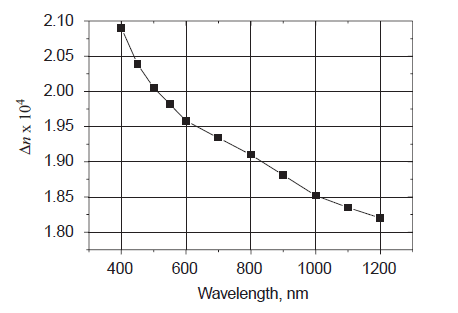
Fig. 1. Wavelength dependence of the birefringent index of one-axis-stretched PMMA.
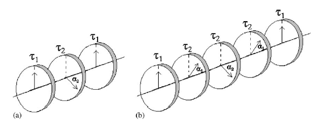
Fig. 2. Design of waveplates: (a) achromatic; (b) super-achromatic.
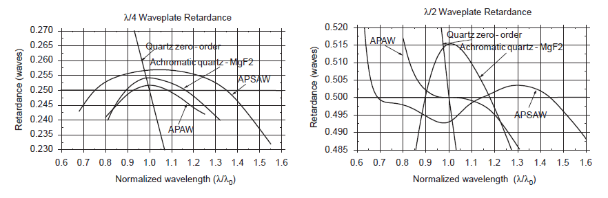
Fig. 3. Wavelength dependences of the retardance of different types of waveplates.
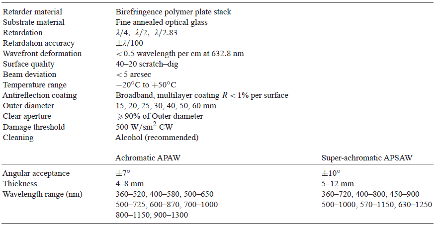
Table 1. List of technical characteristics of achromatic and super-achromatic zero-order waveplates manufactured by “Astropribor”

Fig. 4. Wavelength dependence of the transmittance coefficient of waveplates.
References